
Page 405 - Power Electronics Handbook
P. 405
394 Power semiconductor circuit applications
3-phase supply
Rotor
Stator
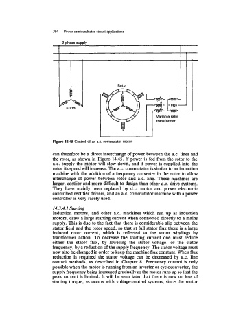
Figure 14.45 Control of an a.c. commutator motor
can therefore be a direct interchange of power between the a.c. lines and
the rotor, as shown in Figure 14.45. If power is fed from the rotor to the
a.c. supply the motor will slow down, and if power is supplied into the
rotor its speed will increase. The a.c. commutator is similar to an induction
machine with the addition of a frequency converter in the rotor to allow
interchange of power between rotor and a.c. line. These machines are
larger, costlier and more difficult to design than other a.c. drive systems.
They have mainly been replaced by d.c. motor and power electronic
controlled rectifier drivers, and an a.c. commutator machine with a power
controller is very rarely used.
14.3.4.1 Starting
Induction motors, and other a.c. machines which run up as induction
motors, draw a large starting current when connected directly to a mains
supply. This is due to the fact that there is considerable slip between the
stator field and the rotor speed, so that at full stator flux there is a large
induced rotor current, which is reflected to the stator windings by
transformer action. To decrease the starting current one must reduce
either the stator flux, by lowering the stator voltage, or the stator
frequency, by a reduction of the supply frequency. The stator voltage must
now also be changed in order to keep the machine flux constant. When flux
reduction is required the stator voltage can be decreased by a.c. line
control methods, as described in Chapter 8. Frequency control is only
possible when the motor is running from an inverter or cycloconverter, the
supply frequency being increased gradually as the motor runs up so that the
peak current is limited. It will be seen later that there is now no loss of
starting tdrque, as occurs with voltage-control systems, since the motor