
Page 407 - Power Electronics Handbook
P. 407
3% Power semiconductor circuit applications
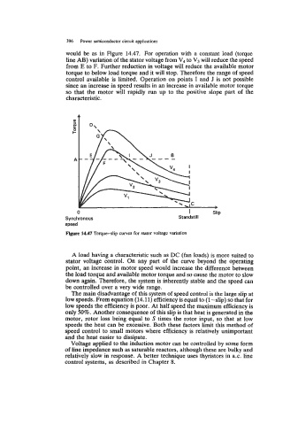
would be as in Figure 14.47. For operation with a constant load (torque
line AB) variation of the stator voltage from V4 to V3 will reduce the speed
from E to F. Further reduction in voltage will reduce the available motor
torque to below load torque and it will stop. Therefore the range of speed
control available is limited. Operation on points I and J is not possible
since an increase in speed results in an increase in available motor torque
so that the motor will rapidly run up to the positive slope part of the
characteristic.
A
m
b
0 I Slip
Synchronous Standstill
speed
Flgure 14.47 Torque-slip curves for stator voltage variation
A load having a characteristic such as DC (fan loads) is more suited to
stator voltage control. On any part of the curve beyond the operating
point, an increase in motor speed would increase the difference between
the load torque and available motor torque and so cause the motor to slow
down again. Therefore, the system is inherently stable and the speed can
be controlled over a very wide range.
The main disadvantage of this system of speed control is the large slip at
low speeds. From equation (14.11) efficiency is equal to (1 -slip) so that for
low speeds the efficiency is poor. At half speed the maximum efficiency is
only 50%. Another consequence of this slip is that heat is generated in the
motor, rotor loss being equal to S times the rotor input, so that at low
speeds the heat can be excessive. Both these factors limit this method of
speed control to small motors where efficiency is relatively unimportant
and the heat easier to dissipate.
Voltage applied to the induction motor can be controlled by some form
of line impedance such as saturable reactors, although these are bulky and
relatively slow in response. A better technique uses thyristors in a.c. line
control systems, as described in Chapter 8.