
Page 406 - Power Electronics Handbook
P. 406
Electrical machine control 395
flux is kept constant by automatic adjustment of the supply voltage. When
a variable-frequency supply is available for starting, synchronous and
reluctance motors need not run up as induction machines since they can
lock onto the stator field at low speeds, and then run up to full speed in
synchronism.
14.3.4.2 Control
The most usual operating mode for synchronous and reluctance motors is
when they are rotating at the synchronous speed of the stator field.
Therefore the speed of these machines can only be varied by changing the
frequency of the stator supply. The same considerations apply to an
induction motor, but due to its construction there are four methods which
may be used to control it, as follows.
(I) Excitation field strength control
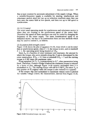
Figure 14.46 shows the plot of equation (14. lo), from which it can be noted
that at synchronous speed, when S = 0, the torque is zero, and at standstill
S = 1, the operating point being located at l/S,.
Since S, is a function of rotor resistance and reactance, the amount by
which the torque-slip curve extends along the X axis is determined by the
rotor construction. If S, = 0.2 then at standstill S/S, = 5 and the starting
torque is 0.385 times the maximum value.
From equation (14.7), T, is proportional to ElZ, other parameters being
fixed. Therefore, if stator voltage is halved the maximum torque is reduced
by a factor of four, although Figure 14.46 remains unchanged since it is
normalised to T,. The starting torque will still be 0.385T, but since T, is
one quarter of its original value the torque is also reduced to a quarter.
If the torque-slip (not normalised to maximum values) curve is plotted
for variable voltage control, the characteristics, derived from Figure 14.46,
I I 1 1 I 1
-
1.0
-
0.8
- -
0.6
E
I-
I- -
0.4
0.2.
I I 1 I I 1
01 I 2 3 4 5 6 7 8 9 IO
SlS,
Figure 14.46 Normalized torque-slip curve