Page 55 - Power Electronics Handbook
P. 55

48   Power semiconductor devices


                                Gate @                        Auxiliary        thyristor
                                             Cathode
                                                                               Main
                                                              thyristor


                                                                         (d)
                                                                      Regenerative
                               Main    Auxiliary              Trigger   source
                               cathode   cathode   Qate                         Regeneratbe


                                          Anode
                                       (e)


                                                                       Anode current


                          Conducting
                          Conducting
                          region
                          region
                          rssiatance
                          rssiatance
                                      (B)    Anode                       (h)
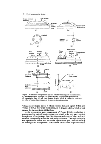
                        Mpre 1.26 Thyristor configurations: (a) dice with bevelled edge; (b) shorted-emitter;
                        (c) interdigitated gate; (d) amplifying gate schematic; (e) amplifying gate structure;
                        (f)  regenerative gate;  (g)  cell  cross  section  showing  effect of  emitter lip  resistance;
                        (h) effect of emitter lip resistance on the current-time  characteristic

                        voltage is developed across it which opposes the gate signal. If  the gate
                        voltage is low, it may even be reversed, as in  Figure 1.26(h), which would
                        reduce the turn-on time still further.
                          In  the  regenerative gate  arrangement of  Figure  1.26(f)  conduction is
                        commenced by a signal on the trigger gate, which is the only gate terminal
                        brought out of the package. Once anode-to-cathode current starts to flow it
                        causes a voltage drop across the emitter lip resistance. This is picked up by
                        the regenerative source and fed to the regenerative gate, which is usually
                        an interdigitated arrangement. The external circuit needs to provide only a
   50   51   52   53   54   55   56   57   58   59   60