
Page 197 - Power Electronics Handbook
P. 197
I
I88 Phase-controlled rectification and inversion
Group A
I
,Load
Group B
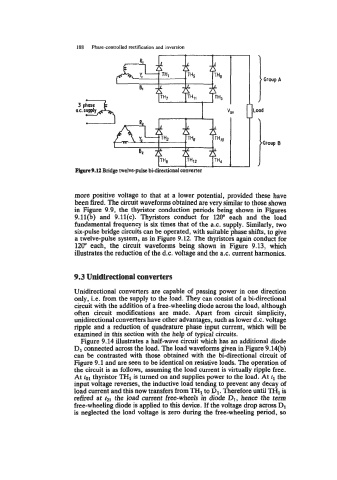
Figure 9.12 Bridge twelve-pulse bi-directional converter
more positive voltage to that at a lower potential, provided these have
been fired. The circuit waveforms obtained are very similar to those shown
in Figure 9.9, the thyristor conduction periods being shown in Figures
9.11(b) and 9.ll(c). Thyristors conduct for 120" each and the load
fundamental frequency is six times that of the a.c. supply. Similarly, two
six-pulse bridge circuits can be operated, with suitable phase shifts, to give
a twelve-pulse system, as in Figure 9.12. The thyristors again conduct for
1200 each, the circuit waveforms being shown in Figure 9.13, which
illustrates the reduction of the d.c. voltage and the a.c. current harmonics.
9.3 Unidirectional converters
Unidirectional converters are capable of passing power in one direction
only, i.e. from the supply to the load. They can consist of a bi-directional
circuit with the addition of a free-wheeling diode across the load, although
often circuit modifications are made. Apart from circuit simplicity,
unidirectional converters have other advantages, such as lower d.c. voltage
ripple and a reduction of quadrature phase input current, which will be
examined in this section with the help of typical circuits.
Figure 9.14 illustrates a half-wave circuit which has an additional diode
D1 connected across the load. The load waveforms given in Figure 9.14(b)
can be contrasted with those obtained with the bi-directional circuit of
Figure 9.1 and are seen to be identical on resistive loads. The operation of
the circuit is as follows, assuming the load current is virtually ripple free.
At fol thyristor TH1 is turned on and supplies power to the load. At fl the
input voltage reverses, the inductive load tending to prevent any decay of
load current and this now transfers from TH1 to D1. Therefore until TH1 is
refired at fzl the load current free-wheels in diode D1, hence the term
free-wheeling diode is applied to this device. If the voltage drop across D1
is neglected the load voltage is zero during the free-wheeling period, so