
Page 199 - Power Electronics Handbook
P. 199
190 Phase-controlled rectification and inversion
Current in 0,
(d)
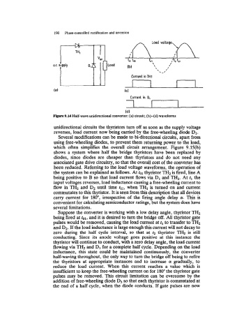
Figure 9.14 Half-wave unidirectional converter: (a) circuit; (b)-(d) waveforms
unidirectional circuits the thyristors turn off as soon as the supply voltage
reverses, load current now being carried by the free-wheeling diode D1.
Several modifications can be made to bi-directional circuits, apart from
using free-wheeling diodes, to prevent them returning power to the load,
which often simplifies the overall circuit arrangement. Figure 9.15(b)
shows a system where half the bridge thyristors have been replaced by
diodes, since diodes are cheaper than thyristors and do not need any
associated gate drive circuitry, so that the overall cost of the converter has
been reduced. Referring to the load voltage waveforms, the operation of
the system can be explained as follows. At tol thyristor THz is fired, line A
being positive to B so that load current flows via D1 and THz. At tl the
input voltages reverses, load inductance causing a free-wheeling current to
flow in THz and Dz until time til, when TH1 is turned on and current
commutates to this thyristor. It is seen from this description that all devices
carry current for 180", irrespective of the firing angle delay a. This is
convenient for calculating semiconductor ratings, but the system does have
several limitations.
Suppose the converter is working with a low delay angle, thyristor THz
being fired at tol, and it is desired to turn the bridge off. All thyristor gate
pulses would be removed, causing the load current at tl to transfer to TH2
and DZ. If the load inductance is large enough this current will not decay to
zero during the half cycle interval, so that at rz thyristor TH2 is still
conducting. Since its anode voltage goes positive at this instance the
thyristor will continue to conduct, with a zero delay angle, the load current
flowing via THZ and D1 for a complete half cycle. Depending on the load
inductance, this state could be maintained continuously, the converter
half-waving throughout, the only way to turn the bridge off being to refire
the thyristors at appropriate instances and to increase a gradually, to
reduce the load current. When this current reaches a value which is
insufficient to keep the free-wheeling current on for 180" the thyristor gate
pulses may be removed. This circuit limitation can be overcome by the
addition of free-wheeling diode D3 so that each thyristor is commutated at
the end of a half cycle, when the diode conducts. If gate pulses are now