
Page 198 - Power Electronics Handbook
P. 198
Unidirectional converters 189
Group d
Phase volta es of
"Itaqy--p$
iPp\y current
/ -Fundamental
supply current
,
0; Q 90'
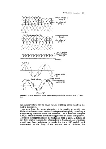
Figure 9.13 Circuit waveforms for the bridge twelve-pulse bi-directional converter of Figure
9.12
that the converter is now no longer capable of passing power back from the
load to the supply.
As seen from the above discussion, it is possible to modify any
bi-directional converter to unidirectional operation simply by connecting a
free-wheeling diode across the load terminals. This is illustrated in Figure
9.15(a), which shows the modification applied to the circuit of Figure 9.4.
Thyristors in diagonal arms of the bridge are fired in pairs, as before, at
any delay angle a: required, but whereas for a bi-directional converter these
would have been maintained in conduction for a 180" period, until
commutated by the firing of the opposite pair of thyristors, for