
Page 203 - Power Electronics Handbook
P. 203
194 Phase-controlled rectification and inversion
9.2, for instance, will not operate correctly if one thyristor is replaced by a
diode, all such systems requiring a free-wheeling diode for unidirectional
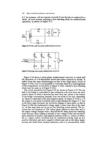
operation, as shown in Figure 9.17.
+
Figure 9.17 Push-pull two-pulse unidirectional converter
3
ax. .oad
Figure 9.18 Bridge three-pulse unidirectional converter
Figure 9.18 shows a three-phase unidirectional converter in which half
the thyristors of a bi-directional circuit have been replaced by diodes. It
suffers from the same disadvantages as that of the single-phase circuit of
Figure 9.15(b), but it is not possible to overcome these by a rearrangement
of the components, as was done in Figure 9.15(d). Instead a free-wheeling
diode must be used, as in Figure 9.13~).
The circuit waveforms for Figure 9.18 are shown in Figure 9.19. The top
half of the bridge is controlled so that conduction will occur from the most
positive phase in which a thyristor has been fired, the current in the bottom
of the bridge commutating naturally from one diode to the next, depending
on which is connected to the most negative phase. In Figure 9.19 for a = 0
the output is a six-pulse waveform such as that obtained for Figure 9.11, but
as the delay angle increases, the waveform changes to three-pulse, so that in
Figure 9.19(b) the fundamental voltage ripple is three times that of the input
a.c. At this stage there are as yet no free-wheeling current periods. The a.c.
current has two durations of 120" whose phase relation to each other and to
the supply voltage changes with a. Beyond the 60" delay point free-wheeling
times increase, these leading to periods of zero voltage in the load waveform
and a reduction of positive and negative portions of the a.c. current. In effect,
the a.c. supply current waveform may be considered as being made up of a
positive (thyristor) part and a negative (diode) part and as the delay angles
increase the diode block remains stationary, since it is uncontrolled, whilst