
Page 207 - Power Electronics Handbook
P. 207
198 Phase-controlled rectification and inversion
current. Figure 9.21(c) shows the effect of discontinuous load current
during the inverting mode of the converter, assuming that the load has an
internal back e.m.f. which provides the inverter voltage.
In order to ensure that the load current never becomes discontinuous it
is possible to analyse the converter circuit to determine the minimum load
inductance required under various firing angles, such an analysis
depending on the value of load back e.m.f. and being involved, although it
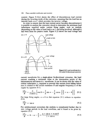
has been done for passive loads. Figure 9.22 shows the load voltage and
Figure 9.22 Load waveforms for a
two-pulse bi-directional converter
current waveforms for a single-phase bi-directional converter, the load
current reaching a minimum value at the intersection points of the
instantaneous and mean d.c. waveforms. It can be shown that the value of
critical inductance L, required to prevent this current from falling below
zero is related to the circuit resistance R and angular frequency o of the
supply by equation (9.1).
oLc = x 8 2 2 (9.1)
- - + -sin a: - -cosa: {s + (Y - e}]
R 2cos a: [COS x x
For large firing angles, a = 8 so that equation (9.1) reduces to equation
(9.2).
For unidirectional converters the analysis is complicated further due to
zero voltage periods in the load waveform, and is found to be given by
equation (9.3).
-- - e-ar--+ a: + sin a: + IT: cos 0 (9.3)
IT:
WLC
R 2 1 + cos a: