
Page 205 - Power Electronics Handbook
P. 205
196 Phase-controlled rectification and inversion
the thyristor block moves towards it. Beyond 60” delay the two overlap to an
increasing extent, resulting in an increase in the free-wheeling period.
It has been stated above that an unidirectional wave has a lower d.c.
voltage content, owing to the absence of negative portions of the
waveform. However, for high pulse numbers it is seen above that there can
be a reduction of ripple frequency by a factor of 2 from that of
bi-directional converters. There is now obviously a compromise situation
where, depending on the range of control voltage required, one converter
would give lower ripple output than another. Ripple content from
converter circuits are considered again in following sections.
9.4 Discontinuous load current
In the previous sections it has been assumed that, apart from resistive
loads, the load current has been continuous during a cycle of operation.
If this is not the case then the load voltage waveform will be modified
from those illustrated earlier. Generally, these systems are not easy to
analyse since the output conditions are dependent on the load.
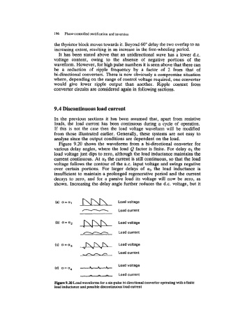
Figure 9.20 shows the waveforms from a bi-directional converter for
various delay angles, where the load Q factor is finite. For delay a1 the
load voltage just dips to zero, although the load inductance maintains the
current continuous. At a2 the current is still continuous, so that the load
voltage follows the contour of the a.c. input voltage and swings negative
over certain portions. For larger delays of cy3 the load inductance is
insufficient to maintain a prolonged regenerative period and the current
decays to zero, and for a passive load its voltage will now be zero, as
shown. Increasing the delay angle further reduces the d.c. voltage, but it
-
T\[u\
(a) a=al Load voltage
Load
current
(b) a=a2 vh.bwh
Load voltage
- current
Load
,vw”
(c) a=a3 - Load voltage
- Load current
.- .- .- Load voltage
(d) a= ag
Load current
Fbre 9.u) Load waveforms for a six-pulse bi-directional converter operating with a finite
load inductance and possible discontinuous load current