
Page 208 - Power Electronics Handbook
P. 208
Discontinuous load current 199
As before, there are two operating conditions according to whether a is
smaller or larger than a critical value (35.5"), which gives a = 8. In this case
equation (9.3) reduces to equation (9.4).
-- - -- + a+sina+ncosa (9.4)
JC
WLC
R 2 1 + cos a
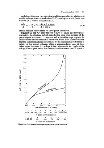
Similar analysis can be made for three-phase converters.
Figures 9.23 and 9.24 show the plot of LJR for single- and three-phase
converters, the abscissae in both cases having been given in terms of the
percentage of maximum d.c. output as well as the delay angle required for
unidirectional and bi-directional converters. From these curves it is seen
that the critical inductance requirement for bi-directional circuits tends to
infinity at low output voltages, which is understandable, since at these
delay angles the mean d.c. voltage is low, whereas the a.c. ripple on the
voltage is at its peak value. For unidirectional converters the ax. ripple is
70 -
50 -
30 -
z
0
0
m
m
- -
b
L
c 10-
0
c
C c: 7-
E
U
100 80 60 40 20 0
Per cent of max. d.c. voltage
1 1 I I I I I 1 1 1 1
0 30 45 60 75 90 105 120 135150180
a Scale for uni-directional
1 1 I I I I I I
0 20 30 45 60 70 80 90
a Scale for bi-directional
Prprc 9.23 Critical inductance requirements for two-pulse converters