
Page 213 - Power Electronics Handbook
P. 213
204 Phasecontrolled rectification and inversion
D1 TH4 D1 TH3 D1 TH4
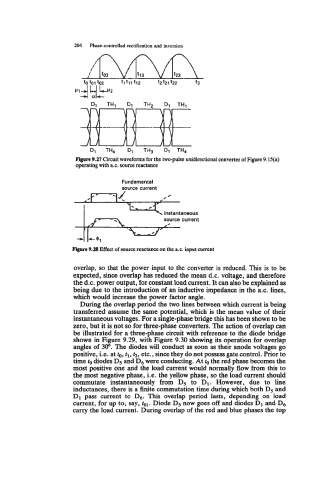
Fbprr 9.27 Circuit waveforms for the two-pulse unidirectional converter of Figure 9.15(a)
operating with a.c. source reactance
Fundamental
source current
i source taneous current
Figwe 9.28 Effect of source reactance on the a.c. input current
overlap, so that the power input to the converter is reduced. This is to be
expected, since overlap has reduced the mean d.c. voltage, and therefore
the d.c. power output, for constant load current. It can also be explained as
being due to the introduction of an inductive impedance in the a.c. lines,
which would increase the power factor angle.
During the overlap period the two lines between which current is being
transferred assume the same potential, which is the mean value of their
instantaneous voltages. For a single-phase bridge this has been shown to be
zero, but it is not so for three-phase converters. The action of overlap can
be illustrated for a three-phase circuit with reference to the diode bridge
shown in Figure 9.29, with Figure 9.30 showing its operation for overlap
angles of 30". The diodes will conduct as soon as their anode voltages go
positive, i.e. at to, tl, t2, etc., since they do not possess gate control. Prior to
time to diodes D5 and D6 were conducting. At the red phase becomes the
most positive one and the load current would normally flow from this to
the most negative phase, Le. the yellow phase, so the load current should
commutate instantaneously from D5 to D1. However, due to line
inductances, there is a finite commutation time during which both D5 and
D1 pass current to D6. This overlap period lasts, depending on load
current, for up to, say, tal. Diode D5 now goes off and diodes D1 and D6
carry the load current. During overlap of the red and blue phases the top