
Page 206 - Power Electronics Handbook
P. 206
Discontinuous load current 197
also reduces the peak load current so that the regeneration period is
shortened.
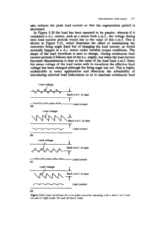
In Figure 9.20 the load has been assumed to be passive, whereas if it
contained a d.c. source, such as a motor back e.m.f., the voltage during
zero load current periods would rise to the value of this e.m.f. This is
shown in Figure 9.21, which illustrates the effect of maintaining the
converter firing angle fixed but of changing the load current, as would
normafly happen in a d.c. motor under variable torque conditions. The
shape of the load waveform is seen to change. During continuous load
current periods it follows that of the a.c. supply, but when the load current
becomes discontinuous it rises to the value of the load back e.m.f. Since
the mean voltage of the load varies with its waveform the effective load
voltage has been changed although the firing angle has not. This is highly
undesirable in many applications and illustrates the advisability of
introducing external load inductances so as to maintain continuous load
Load voltage
\h A 1
Y U Y
Back e.m.f. of load
-nh-n Load current
(8)
-
%A Load voltage
Back e.m.f. of load
(b) Loadcurrent
Load voltage
I 1
I
Back e.m.f. of load
-7
-a_--
Load current
(C)
Load voltage I
Back e.m.f. of load
\I("N\f
Load current
(d)
Figure 9.21 Laad waveforms for a six-pulse converter operating with a back e.m.f. load:
(a) and (c) light loads; @) and (d) heavy loads