
Page 70 - Power Electronics Handbook
P. 70
Semiconductor thermal characteristics 63
(iv) Losses in the control terminal of the power semiconductor. The loss
in the base of a transistor has already been considered as part of the
forward conduction loss in item (i) above, since it is always present
whilst the device is on. However, devices such as thyristors need only
be pulse fired, so the gate power loss can be separated from the
forward conduction loss. Four parameters are now usually defined;
the peak gate power PGM, i.e. the maximum value of the product of
the forward gate current and voltage which is permissible; the
average gate power PG,,,, which is the maximum value of the
forward gate current and voltage averaged over one cycle; and peak
reverse gate power PGMR and average reverse gate power PGR(*V),
which are the corresponding reverse values. Figure 1.23 shows the
peak gate power curves within which the gate drive locus needs to
stay.
2.3 Semiconductor thermal characteristics
A power semiconductor mounted on a heatsink can be analysed by analogy
with electrical circuits in which the flow of current is replaced by heat
transfer and the electrical impedances by thermal resistances. The unit of
heat transfer is measured in joules per seconds or watts, and the unit of
thermal resistance is in degrees centigrade per watt. Therefore if Q is the
thermal power in watts being dissipated within a device, and dT is the
temperature difference 8ctosp the device in degrees Centigrade, then the
thermal resistance Rh of the device is given by equation (2.1).
R& = dT/Q (WW) (2.1)
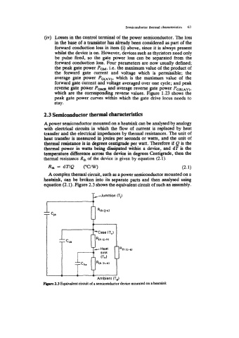
A complex thermal circuit, such as a power semiconductor mounted on a
heatsink, can be broken into its separate parts and then analysed using
equation (2.1). Figure 2.3 shows the equivalent circuit of such an assembly.
PJunction (Ti)
zz cca Rth Ic-h)
zzcha Rth (h-a)
A - -
Ambient (T,)
2.3 Equivalent circuit of a semiconductor device mounted on a heatsink