
Page 71 - Power Electronics Handbook
P. 71
64 Thermal design
If Tj and Tc are the temperatures of the semiconductor junction and its
case, and the thermal resistance between junction and case, then
for a power flow of Q W between junction and case the thermal resistance
is given by equation (2.2).
&h(j -c) = (Tj - TcVQ (2.2)
Similarly, the other thermal resistances between case and heatsink, and
heatsink and ambient, can be obtained. Figure 2.3 also shows the thermal
capacitances (Cj,, etc.) which can generally be ignored in any r.m.s.
calculation and are only used for transient analysis. The thermal resistance
between case and ambient is usually large compared to that through the
heatsink, so that it too can be ignored. The equivalent circuit therefore
simplifies to three elements in series, and for this total system the thermal
resistance between semiconductor junction and ambient is given by
equation (2.3) and the temperature rise by equation (2.4).
Rth(j -a) = &h(j - c) + Rth(c - h) -k Rth(h - a) (2.3)
Tj - Ta = Q Rth, -a) (2.4)
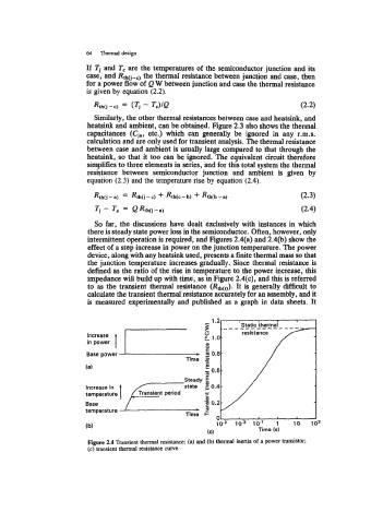
So far, the discussions have dealt exclusively with instances in which
there is steady state power loss in the semiconductor. Often, however, only
intermittent operation is required, and Figures 2.4(a) and 2.4(b) show the
effect of a step increase in power on the junction temperature. The power
device, along with any heatsink used, presents a finite thermal mass so that
the junction temperature increases gradually. Since thermal resistance is
defined as the ratio of the rise in temperature to the power increase, this
impedance will build up with time, as in Figure 2.4(c), and this is referred
to as the transient thermal resistance (Rth(& It is generally difficult to
calculate the transient thermal resistance accurately for an assembly, and it
is measured experimentally and published as a graph in data sheets. It
Figure 2.4 Transient thermal resistance: (a) and (b) thermal inertia of a power transistor;
(c) transient thermal resistance cwe