
Page 72 - Power Electronics Handbook
P. 72
Semiconductor thermal characteristics 65
should be noted that this information applies for a fully conducting cell,
such as when operating into fault conditions, and it cannot be used for
power devices which are in the process of being turned on, since now the
turned-on area is still spreading.
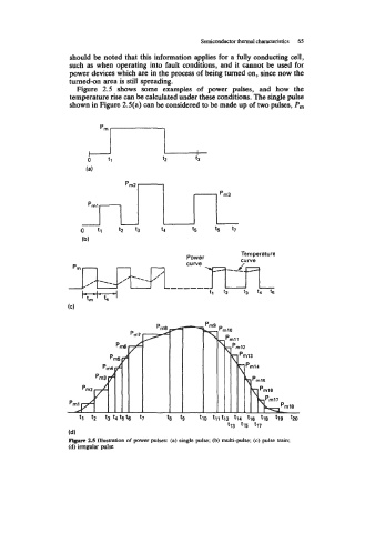
Figure 2.5 shows some examples of power pulses, and how the
temperature rise can be calculated under these conditions. The single pulse
shown in Figure 2.5(a) can be considered to be made up of two pulses, P,,,
t9 tll t12 t14 t16 t18 t19 tZO
t13 t15 t17
(4
Figure 2.5 Illustration of power pulses: (a) single pulse.; (b) multi-pulse; (c) pulse train;
(d) implar pulse