
Page 142 - Power Quality in Electrical Systems
P. 142
124 Chapter Eight
V mh
V m
I o
X
+ +
V o V m X m X c R
– – I m I c I n I m I mh I m
X characteristics
m
(a) (b)
(capacitor current)
I ch
I c
I o V o V oh (line voltage)
JI X
o
I oh
I n I nh V m V mh (load voltage)
(load current)
I m
(reactor current)
I mh
(c)
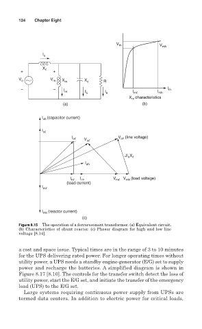
Figure 8.15 The operation of a ferroresonant transformer. (a) Equivalent circuit.
(b) Characteristics of shunt reactor. (c) Phasor diagram for high and low line
voltage [8.14].
a cost and space issue. Typical times are in the range of 3 to 10 minutes
for the UPS delivering rated power. For longer operating times without
utility power, a UPS needs a standby engine-generator (E/G) set to supply
power and recharge the batteries. A simplified diagram is shown in
Figure 8.17 [8.10]. The controls for the transfer switch detect the loss of
utility power, start the E/G set, and initiate the transfer of the emergency
load (UPS) to the E/G set.
Large systems requiring continuous power supply from UPSs are
termed data centers. In addition to electric power for critical loads,