
Page 140 - Power Quality in Electrical Systems
P. 140
122 Chapter Eight
A
Source B
C
a1 Load Load Load
a2 3d harmonic
currents
c2
c1 b2
b1
N
Transformer
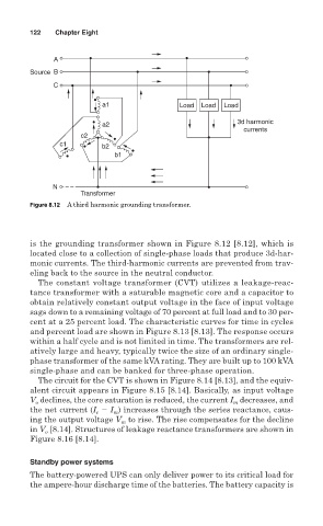
Figure 8.12 A third harmonic grounding transformer.
is the grounding transformer shown in Figure 8.12 [8.12], which is
located close to a collection of single-phase loads that produce 3d-har-
monic currents. The third-harmonic currents are prevented from trav-
eling back to the source in the neutral conductor.
The constant voltage transformer (CVT) utilizes a leakage-reac-
tance transformer with a saturable magnetic core and a capacitor to
obtain relatively constant output voltage in the face of input voltage
sags down to a remaining voltage of 70 percent at full load and to 30 per-
cent at a 25 percent load. The characteristic curves for time in cycles
and percent load are shown in Figure 8.13 [8.13]. The response occurs
within a half cycle and is not limited in time. The transformers are rel-
atively large and heavy, typically twice the size of an ordinary single-
phase transformer of the same kVA rating. They are built up to 100 kVA
single-phase and can be banked for three-phase operation.
The circuit for the CVT is shown in Figure 8.14 [8.13], and the equiv-
alent circuit appears in Figure 8.15 [8.14]. Basically, as input voltage
V declines, the core saturation is reduced, the current I decreases, and
m
o
the net current (I I ) increases through the series reactance, caus-
c
m
to rise. The rise compensates for the decline
ing the output voltage V m
in V [8.14]. Structures of leakage reactance transformers are shown in
o
Figure 8.16 [8.14].
Standby power systems
The battery-powered UPS can only deliver power to its critical load for
the ampere-hour discharge time of the batteries. The battery capacity is