
Page 136 - Power Quality in Electrical Systems
P. 136
118 Chapter Eight
i h
i h i h i h i h i h
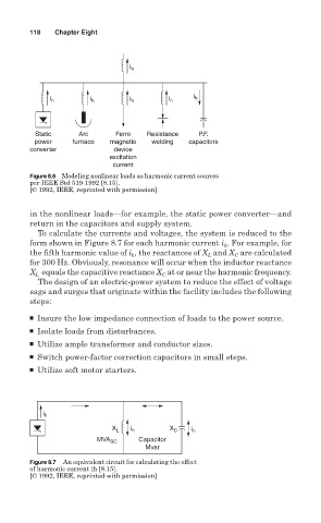
Static Arc Ferro Resistance P.F.
power furnace magnetio welding capacitors
converter device
excitation
current
Figure 8.6 Modeling nonlinear loads as harmonic current sources
per IEEE Std 519-1992 [8.15].
[© 1992, IEEE, reprinted with permission]
in the nonlinear loads—for example, the static power converter—and
return in the capacitors and supply system.
To calculate the currents and voltages, the system is reduced to the
form shown in Figure 8.7 for each harmonic current i . For example, for
h
the fifth harmonic value of i , the reactances of X and X are calculated
C
h
L
for 300 Hz. Obviously, resonance will occur when the inductor reactance
X equals the capacitive reactance X at or near the harmonic frequency.
L
C
The design of an electric-power system to reduce the effect of voltage
sags and surges that originate within the facility includes the following
steps:
■ Insure the low impedance connection of loads to the power source.
■ Isolate loads from disturbances.
■ Utilize ample transformer and conductor sizes.
■ Switch power-factor correction capacitors in small steps.
■ Utilize soft motor starters.
i h
X L i h X C i h
MVA SC Capacitor
Mvar
Figure 8.7 An equivalent circuit for calculating the effect
of harmonic current ih [8.15].
[© 1992, IEEE, reprinted with permission]