
Page 133 - Power Quality in Electrical Systems
P. 133
Methods for Correction of Power-Quality Problems 115
Design of load equipment
Two factors in the design of load equipment can (1) reduce the possibil-
ity of the equipment itself causing a power-quality problem, such as pro-
ducing harmonic currents, and (2) reduce the sensitivity of the
equipment to problems such as voltage sags and outages.
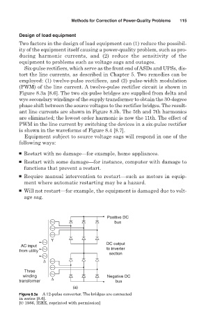
Six-pulse rectifiers, which serve as the front end of ASDs and UPSs, dis-
tort the line currents, as described in Chapter 5. Two remedies can be
employed: (1) twelve-pulse rectifiers, and (2) pulse-width modulation
(PWM) of the line current. A twelve-pulse rectifier circuit is shown in
Figure 8.3a [8.6]. The two six-pulse bridges are supplied from delta and
wye secondary windings of the supply transformer to obtain the 30-degree
phase shift between the source voltages to the rectifier bridges. The result-
ant line currents are shown in Figure 8.3b. The 5th and 7th harmonics
are eliminated; the lowest order harmonic is now the 11th. The effect of
PWM in the line current by switching the devices in a six-pulse rectifier
is shown in the waveforms of Figure 8.4 [8.7].
Equipment subject to source voltage sags will respond in one of the
following ways:
■ Restart with no damage—for example, home appliances.
■ Restart with some damage—for instance, computer with damage to
functions that prevent a restart.
■ Require manual intervention to restart—such as motors in equip-
ment where automatic restarting may be a hazard.
■ Will not restart—for example, the equipment is damaged due to volt-
age sag.
Positive DC
bus
Y
DC output
AC input
from utility to inverter
section
∆
Three
winding Negative DC
transformer ∆ bus
(a)
Figure 8.3a A 12-pulse converter. The bridges are connected
in series [8.6].
[© 1986, IEEE, reprinted with permission]