
Page 138 - Power Quality in Electrical Systems
P. 138
120 Chapter Eight
Normal utility source
Main
CB
Main bus
Non-emerg. UPS input
CB CB
To non-emergency Battery
load charger
Bypass Battery
circuit
Inverter
Bypass
static UPS output
switch Bypass CB
CB
Emerg. AC bus
To emergency AC load
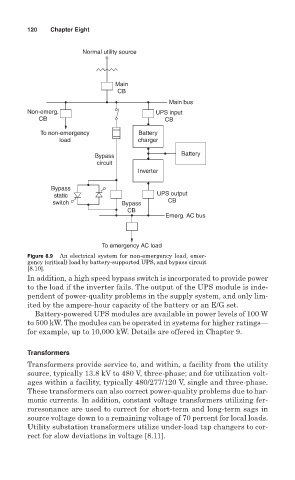
Figure 8.9 An electrical system for non-emergency load, emer-
gency (critical) load by battery-supported UPS, and bypass circuit
[8.10].
In addition, a high speed bypass switch is incorporated to provide power
to the load if the inverter fails. The output of the UPS module is inde-
pendent of power-quality problems in the supply system, and only lim-
ited by the ampere-hour capacity of the battery or an E/G set.
Battery-powered UPS modules are available in power levels of 100 W
to 500 kW. The modules can be operated in systems for higher ratings—
for example, up to 10,000 kW. Details are offered in Chapter 9.
Transformers
Transformers provide service to, and within, a facility from the utility
source, typically 13.8 kV to 480 V, three-phase; and for utilization volt-
ages within a facility, typically 480/277/120 V, single and three-phase.
These transformers can also correct power-quality problems due to har-
monic currents. In addition, constant voltage transformers utilizing fer-
roresonance are used to correct for short-term and long-term sags in
source voltage down to a remaining voltage of 70 percent for local loads.
Utility substation transformers utilize under-load tap changers to cor-
rect for slow deviations in voltage [8.11].