
Page 141 - Power Quality in Electrical Systems
P. 141
100
wout/Ferro Xfmr
80
Percent voltage 60 CBEMA w/Ferro Xfmr
40
20
0
0.1 1 10 100 1000
Time in cycles
(a)
80
70
Input voltage minimum % 60
50
40
30
20
10
0
25 50 75 100
Percent loading of ferroresonant transformer
(b)
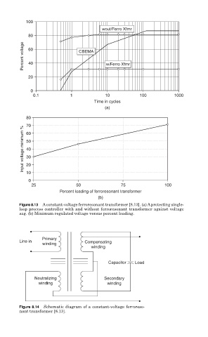
Figure 8.13 A constant-voltage ferroresonant transformer [8.13]. (a) A protecting single-
loop process controller with and without ferroresonant transformer against voltage
sag. (b) Minimum regulated voltage versus percent loading.
Primary
Line in Compensating
winding
winding
Capacitor Load
Neutralizing Secondary
winding winding
Figure 8.14 Schematic diagram of a constant-voltage ferroreso-
nant transformer [8.13].