
Page 166 - Power Quality in Electrical Systems
P. 166
148 Chapter Ten
X 1
Series
transformer
H 1
Figure 10.1 Transformer-type tap
changer for regulating secondary
X o voltage [10.1].
H 2
Neutral
the compensator is smaller and less costly than a UPS. However, it
cannot handle the long-time voltage deviations and total outages that
a battery-powered UPS can.
Principle of Operation
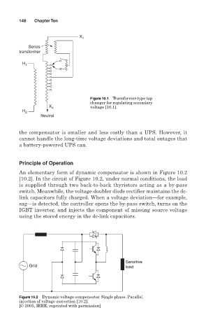
An elementary form of dynamic compensator is shown in Figure 10.2
[10.2]. In the circuit of Figure 10.2, under normal conditions, the load
is supplied through two back-to-back thyristors acting as a by-pass
switch. Meanwhile, the voltage-doubler diode rectifier maintains the dc-
link capacitors fully charged. When a voltage deviation—for example,
sag—is detected, the controller opens the by-pass switch, turns on the
IGBT inverter, and injects the component of missing source voltage
using the stored energy in the dc-link capacitors.
Sensitive
Grid load
Figure 10.2 Dynamic voltage compensator. Single phase. Parallel
injection of voltage correction [10.2].
[© 2005, IEEE, reprinted with permission]