
Page 171 - Power Quality in Electrical Systems
P. 171
Dynamic Voltage Compensators 153
For balanced line voltages, v 1 and v zero. The phase-locked loop
q
d
circuit PLL detects the line voltage v , operates in synchronism with the
s
line voltage, and calculates the phase angle u , which is used in the
s
transformation of v .
s
The voltages v and v are compared with reference voltages v d * and
d
q
*
q
d
v q to yield the error voltages v and v , which represent the devia-
tion of the source voltage from the referenced waveform and amplitude.
The voltage sag detection circuit responds to a value of v that exceeds
d
a preset value—for example, 2 percent. The circuit opens the by-pass
switch (Gate Lock) and feeds gate signals to the compensating con-
verter. The error voltages v and v undergo an inverse d-q transfor-
d
q
mation to produce a three-phase set of deviation voltages (v, which
become the three-phase reference voltages v c * for the converter that
provides the components of compensation voltage.
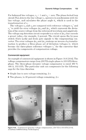
Commercial equipment
An example of commercial equipment is shown in Figure 10.8 [10.6]. The
voltage compensators range from 250 VA single-phase to 333 kVA three-
phase. The three-phase dynamic voltage compensator is rated 480 V,
400 A, 333 kVA. The particular unit can compensate for the following
sags for the time duration:
■ Single line to zero voltage remaining, 2 s
■ Two phases, to 30 percent voltage remaining, 2 s
Figure 10.8 Commercial dynamic voltage compensators, 250 VA to 333 kVA [10.6].
[Courtesy SoftSwitching Technologies]