
Page 170 - Power Quality in Electrical Systems
P. 170
152 Chapter Ten
% of total Spike Voltage Transformerless UPS
Type of event PQ events suppressor regulator DySC systems
Spikes & surges 5% Solves Solves Solves Solves
Sag to 80% 35% No Solves Solves Solves
Sag from 50–80% 45% No No Solves Solves
Interruption 7% No No Solves Solves
0–0.15 s
Interruption 4% No No No Solves
0.15–500 s
>500 sec outage 4% No No No No
Total PQ events 100% 5% 40% 92% 96%
solved
kVA range 1–1000 kVA 1–200 kVA 1–2000 kVA 0.2–1000 kVA
kVA/lb 1–10 0.02–0.03 0.2–1.0 0.01–0.02
kVA/ft 3 500 1–2 10–50 0.3–1
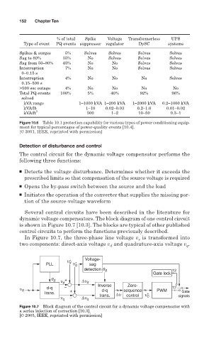
Figure 10.6 Table 10.1 protection capability for various types of power conditioning equip-
ment for typical percentages of power-quality events [10.4].
[© 2001, IEEE, reprinted with permission]
Detection of disturbance and control
The control circuit for the dynamic voltage compensator performs the
following three functions:
■ Detects the voltage disturbance. Determines whether it exceeds the
prescribed limits so that compensation of the source voltage is required
■ Opens the by-pass switch between the source and the load
■ Initiates the operation of the converter that supplies the missing por-
tion of the source-voltage waveform
Several control circuits have been described in the literature for
dynamic voltage compensators. The block diagram of one control circuit
is shown in Figure 10.7 [10.3]. The blocks are typical of other published
control circuits to perform the functions previously described.
is transformed into
In Figure 10.7, the three-phase line voltage v s
two components: direct-axis voltage v and quadrature-axis voltage v .
q
d
u ∗ Voltage-
PLL d u ∗ q sag
detection q S 12
Gate lock
q S u d + ∆u d
Zero-
u S d-q − Inverse sequence PWM 12
d-q
trans. + ∆u ∗ Gate
u q − ∆u q trans. control u C signals
Figure 10.7 Block diagram of the control circuit for a dynamic voltage compensator with
a series injection of correction [10.3].
[© 2005, IEEE, reprinted with permission]