
Page 192 - Power Quality in Electrical Systems
P. 192
174 Chapter Twelve
Power circuit 480 V
Three-phase
CB 1
60 Hz
L1
L2
L3
480 V
C1-1 C1–2 C1–3
CB 2 XFMR 1
120 V
OL 1 OL 2 OL 3
PB 1 PB 2
C1 OL 1 OL 3
M
OL 2
Motor 1
C1-AUX
Control circuit
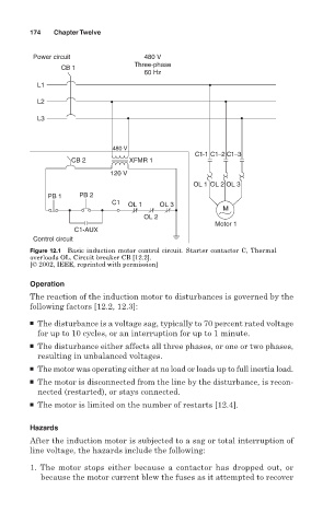
Figure 12.1 Basic induction motor control circuit. Starter contactor C, Thermal
overloads OL. Circuit breaker CB [12.2].
[© 2002, IEEE, reprinted with permission]
Operation
The reaction of the induction motor to disturbances is governed by the
following factors [12.2, 12.3]:
■ The disturbance is a voltage sag, typically to 70 percent rated voltage
for up to 10 cycles, or an interruption for up to 1 minute.
■ The disturbance either affects all three phases, or one or two phases,
resulting in unbalanced voltages.
■ The motor was operating either at no load or loads up to full inertia load.
■ The motor is disconnected from the line by the disturbance, is recon-
nected (restarted), or stays connected.
■ The motor is limited on the number of restarts [12.4].
Hazards
After the induction motor is subjected to a sag or total interruption of
line voltage, the hazards include the following:
1. The motor stops either because a contactor has dropped out, or
because the motor current blew the fuses as it attempted to recover