
Page 194 - Power Quality in Electrical Systems
P. 194
176 Chapter Twelve
80
40
Current (A) 0
–40
–80
0 0.05 0.1 0.15 0.2 0.25 0.3
Time (s)
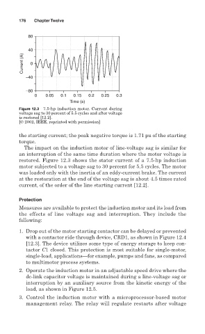
Figure 12.3 7.5-hp induction motor. Current during
voltage sag to 30 percent of 5.5 cycles and after voltage
is restored [12.2].
[© 2002, IEEE, reprinted with permission]
the starting current; the peak negative torque is 1.71 pu of the starting
torque.
The impact on the induction motor of line-voltage sag is similar for
an interruption of the same time duration where the motor voltage is
restored. Figure 12.3 shows the stator current of a 7.5-hp induction
motor subjected to a voltage sag to 30 percent for 5.5 cycles. The motor
was loaded only with the inertia of an eddy-current brake. The current
at the restoration at the end of the voltage sag is about 4.5 times rated
current, of the order of the line starting current [12.2].
Protection
Measures are available to protect the induction motor and its load from
the effects of line voltage sag and interruption. They include the
following:
1. Drop out of the motor starting contactor can be delayed or prevented
with a contactor ride through device, CRD1, as shown in Figure 12.4
[12.3]. The device utilizes some type of energy storage to keep con-
tactor C1 closed. This protection is most suitable for single-motor,
single-load, applications—for example, pumps and fans, as compared
to multimotor process systems.
2. Operate the induction motor in an adjustable speed drive where the
dc-link capacitor voltage is maintained during a line-voltage sag or
interruption by an auxiliary source from the kinetic energy of the
load, as shown in Figure 12.5.
3. Control the induction motor with a microprocessor-based motor
management relay. The relay will regulate restarts after voltage