
Page 195 - Power Quality in Electrical Systems
P. 195
Electric Motor Drive Equipment 177
480 V
CB 2 XFMR 1
120 V
C1
PB 1 PB 2
OL 1 OL 2 OL 3
CRD 1
C1-AUX
Figure 12.4 Control circuit of Figure 12.1 with voltage sag
contactor ride-through device CRD1 [12.2].
[© 2002, IEEE, reprinted with permission]
interruptions based on the thermal state of the motor, as compared with
a count of starts per hour. The relay is suitable for large motors where
the numbers of starts is limited to prevent overheating [12.5].
Adjustable Speed Drives
An adjustable speed drive (ASD) consists of a rectifier, an induction
motor, and a controller. The inverter provides power to the induction
motor at a frequency typically from near zero to 120 Hz, so that the
induction motor speed is adjustable from near zero to twice rated. The
inverter and motor voltage is controlled as the frequency is changed on
a constant volts-per-Hertz basis to maintain constant air-gap flux den-
sity in the motor in so-called constant torque operation.
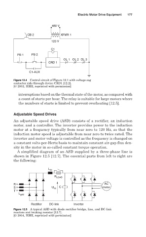
A simplified diagram of an ASD supplied by a three-phase line is
shown in Figure 12.5 [12.7]. The essential parts from left to right are
the following:
L dc
R LOAD
R AC
S U dc C motor
T
L grid
Rectifier DC-link Inverter
Figure 12.5 A typical ASD with diode rectifier bridge, line, and DC-link
reactors and braking resistor [12.7].
[© 2004, IEEE, reprinted with permission]