
Page 200 - Power Quality in Electrical Systems
P. 200
182 Chapter Twelve
Type D
Type C
Balanced
Balanced case
case
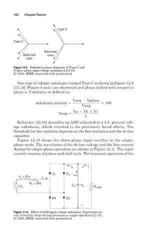
Figure 12.9 Definition phasor diagrams of Types C and
D three-phase input voltage unbalanced [12.10].
[© 2004, IEEE, reprinted with permission]
One type of voltage unbalance termed Type C is shown in Figure 12.9
[12.10]. Phases b and c are shortened and phase shifted with respect to
phase a. Unbalance is defined as:
Vavg 2 Vphase
unbalance percent 5 3 100
Vavg
Va 1 Vb 1 Vc
Vavg 5
3
Reference [12.10] describes an ASD subjected to a 2.5 -percent volt-
age unbalance, which reverted to the previously listed effects. The
threshold for the condition depends on the line reactance and the dc-bus
capacitor.
Figure 12.10 shows the three-phase input rectifier in the single-
phase mode. The waveforms of the dc-bus voltage and the line current
during the single-phase operation are shown in Figure 12.11. The input
current consists of pulses each half cycle. The harmonic spectrum of the
i d + i L
D 1 D 3 i
L = 2La i a cap
s
+
R = 2Ra
s
V s C d V d R LOAD
–
D4 D2
–
Figure 12.10 Effect of ASD input voltage unbalance. Equivalent cir-
cuit of rectifier stage during reversion to single-operation [12.10].
[© 2004, IEEE, reprinted with permission]