
Page 203 - Power Quality in Electrical Systems
P. 203
Electric Motor Drive Equipment 185
Set value: 4
Main circuit
DC voltage Under voltage
H13: Waiting Synchronization
Output time
frequency
(motor speed)
Acceleration
LU trip
Output
(terminals On
Y1 to Y5)
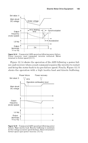
Figure 12.14 Commercial ASD operation following power failure.
Power recovery, reset command, inverter restarted. Motor
returned to former speed [12.11].
Figure 12.14 shows the operation of the ASD following a power fail-
ure and recovery when a reset command requires the inverter to restart
and bring the motor back to its pre-failure speed. Finally, Figure 12.15
shows the operation with a high inertia load and kinetic buffering.
Power failure Power recovery
Set value: 3
H15
Operation continuation level
Main circuit
DC voltage
Output
frequency
(motor speed)
LU trip
Output
(terminals
Y1 to Y5)
Figure 12.15 Commercial ASD operation following power
failure. High inertia load. Kinetic buffering to maintain
dc-bus voltage as motor speed declines. Motor returned to
former speed upon power recovery [12.11].