
Page 205 - Power Quality in Electrical Systems
P. 205
Electric Motor Drive Equipment 187
L dc
R LOAD
R AC
S C motor
T
L dc
BOOST
C b C b
Boost-converter
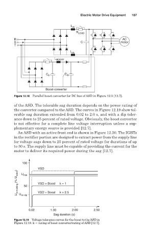
Figure 12.18 Parallel boost converter for DC bus of ASD in Figure 12.5 [12.7].
of the ASD. The tolerable sag duration depends on the power rating of
the converter compared to the ASD. The curves in Figure 12.19 show tol-
erable sag duration extended from 0.02 to 2.0 s, and with a dip toler-
ance down to 25 percent of rated voltage. Obviously, the boost converter
is not effective for a complete line voltage interruption unless a sup-
plementary energy source is provided [12.7].
An ASD with an active front end is shown in Figure 12.20. The IGBTs
in the rectifier portion are designed to extract power from the supply line
for voltage sags down to 25 percent of rated voltage for durations of up
to 30 s. The supply line must be capable of providing the current for the
motor to deliver its required power during the sag [12.7].
100
VSD
U remaining (% U rated ) U dc dip VSD + Boost k = 1
U
min
50
k = 2.5
VSD + Boost
0.02 1.00 2.00 2.50
Sag duration (s)
Figure 12.19 Voltage tolerance curves for the boost to the ASD in
Figure 12.18. k rating of boost converter/rating of ASD [12.7].