
Page 209 - Power Quality in Electrical Systems
P. 209
Standby Power Systems 191
Sample Standby Power Systems
The design of practically every standby power system using the preced-
ing list of components is unique. Each design is based upon the total elec-
trical load (kVA), the reliability and number of utility feeders, the space
available, the reliability requirements for the load power, the selection
of the UPS modules, PDUs, transfer switches and E/G sets, the dollars
available, and other factors. Sample basic systems in order of cost and
complexity include the following:
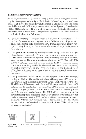
1. Dynamic Voltage Compensator plus a PC: The simplest combi-
nation of a standby power system and a PC is shown in Figure 13.1.
The compensator only protects the PC from short-time utility volt-
age interruptions up to three cycles (50 ms) and sags to 50 percent
for up to 2 s.
2. UPS plus a PC: This configuration (as shown in Figure 13.2) of a single-
phase battery-powered UPS supplying a single personal computer,
is the most common arrangement for preventing voltage distortion,
sags, surges, and interruptions from affecting the PC. Typical UPSs
of 300-W rating, 5-min battery run time, and 120-V terminals in and
out are commercially available. The UPSs are line-interactive (Delta)
or double-conversion (online). The PC plus UPS can be used in an
office, home, factory, or as part of an industrial control or monitor-
ing system.
3. UPS plus a server and PCs: The battery-powered UPS can supply
multiple PCs from the load terminals of a three-phase UPS, as shown
in Figure 13.3, or a local area network (LAN), as shown in Figure 13.4.
The UPS would be rated in the 2-to 10-kVA range, typically 208/120-V
output, and 10-min battery run time. The UPS must have a sufficient
power rating to provide the start-up inrush current to the inputs of
the PCs, servers, and printers. The UPS will shut down for utility
power interruptions exceeding the battery ampere-hour run time. For
maintenance work on the UPS, such as battery replacement or repair,
either the UPS is shut down, or the load is transferred to the utility
source with a synchronized by-pass switch. Some UPSs utilize “hot
swappable batteries.”
AC power Dynam.
Source volt PC
1-phase comp.
Figure 13.1 Block diagram of a dynamic voltage compensator sup-
plying a PC.