
Page 204 - Power Quality in Electrical Systems
P. 204
186 Chapter Twelve
Ride-through
Three-phase Three-phase DC-link Induction
electric utility diode rectifier topology for voltage PWM inverter motor
voltage sags.
V s L s i a a D 1 D 3 D 5 D D C +
L s i b b D 7 8 L db 1 A
L s i c D 9 Q db V a B C IM
c
D D D C 2
4 6 2
V a
V b PWM V a
V c control DC-link
Voltage feedback
sag sense
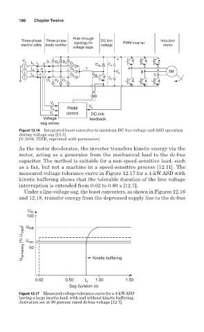
Figure 12.16 Integrated boost converter to maintain DC-bus voltage and ASD operation
during voltage sag [12.3].
[© 2006, IEEE, reprinted with permission]
As the motor decelerates, the inverter transfers kinetic energy via the
motor, acting as a generator from the mechanical load to the dc-bus
capacitor. The method is suitable for a non-speed-sensitive load, such
as a fan, but not a machine in a speed-sensitive process [12.11]. The
measured voltage tolerance curve in Figure 12.17 for a 4-kW ASD with
kinetic buffering shows that the tolerable duration of the line voltage
interruption is extended from 0.02 to 0.80 s [12.7].
Under a line-voltage sag, the boost converters, as shown in Figures 12.16
and 12.18, transfer energy from the depressed supply line to the dc-bus
U dc
100
U remaining (% U rated ) U min Kinetic buffering
U
KIB
50
0.02 0.50 t u 1.00 1.50
Sag duration (s)
Figure 12.17 Measured voltage tolerance curve for a 4-kW ASD
having a large inertia load, with and without kinetic buffering.
Activation set at 90 percent rated dc-bus voltage [12.7].