
Page 214 - Power Quality in Electrical Systems
P. 214
196 Chapter Thirteen
■ NFPA 110-2002, “Standards for Emergency and Standby Power
Systems” [13.3]
■ NFPA 70-2005, “ National Electrical Code” specifically [13.4]
■ Art. 700, “Emergency Systems”
■ Art. 701, “Legally Required Standby Power Systems”
■ Art. 702, “Optional Standby Power Systems”
Component parts of an E/G set installation
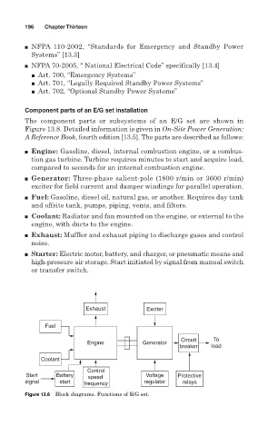
The component parts or subsystems of an E/G set are shown in
Figure 13.8. Detailed information is given in On-Site Power Generation:
A Reference Book, fourth edition [13.5]. The parts are described as follows:
■ Engine: Gasoline, diesel, internal combustion engine, or a combus-
tion gas turbine. Turbine requires minutes to start and acquire load,
compared to seconds for an internal combustion engine.
■ Generator: Three-phase salient-pole (1800 r/min or 3600 r/min)
exciter for field current and damper windings for parallel operation.
■ Fuel: Gasoline, diesel oil, natural gas, or another. Requires day tank
and offsite tank, pumps, piping, vents, and filters.
■ Coolant: Radiator and fan mounted on the engine, or external to the
engine, with ducts to the engine.
■ Exhaust: Muffler and exhaust piping to discharge gases and control
noise.
■ Starter: Electric motor, battery, and charger, or pneumatic means and
high-pressure air storage. Start initiated by signal from manual switch
or transfer switch.
Exhaust Exciter
Fuel
Circuit To
Engine Generator
breaker load
Coolant
Control
Start Battery speed Voltage Protective
signal start frequency regulator relays
Figure 13.8 Block diagrams. Functions of E/G set.