
Page 211 - Power Quality in Electrical Systems
P. 211
Standby Power Systems 193
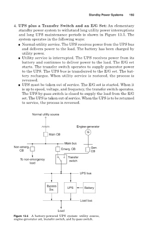
4. UPS plus a Transfer Switch and an E/G Set: An elementary
standby power system to withstand long utility power interruptions
and long UPS maintenance periods is shown in Figure 13.5. The
system operates in the following ways:
■ Normal-utility service. The UPS receives power from the UPS bus
and delivers power to the load. The battery has been charged by
utility power.
■ Utility service is interrupted. The UPS receives power from its
battery and continues to deliver power to the load. The E/G set
starts. The transfer switch operates to supply generator power
to the UPS. The UPS bus is transferred to the E/G set. The bat-
tery recharges. When utility service is restored, the process is
reversed.
■ UPS must be taken out of service. The E/G set is started. When it
is up to speed, voltage, and frequency, the transfer switch operates.
The UPS by-pass switch is closed to supply the load from the E/G
set. The UPS is taken out of service. When the UPS is to be returned
to service, the process is reversed.
Normal utility source
Engine-generator
G
Main CB
Main bus
Non-emerg. Gen.
CB Emerg. CB CB
Transfer
To non-emergency switch
load
UPS bus
Bypass UPS Battery
Sw.
Load bus
Load
Figure 13.5 A battery-powered UPS system: utility source,
engine-generator set, transfer switch, and by-pass switch.