
Page 225 - Power Quality in Electrical Systems
P. 225
Power Quality Measurements 207
∞
µ
I P
I S
I P
N S
Turns
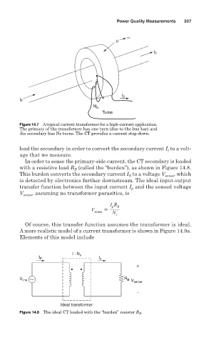
Figure 14.7 A typical current transformer for a high-current application.
The primary of the transformer has one turn (due to the bus bar) and
the secondary has Ns turns. The CT provides a current step-down.
load the secondary in order to convert the secondary current I to a volt-
s
age that we measure.
In order to sense the primary-side current, the CT secondary is loaded
with a resistive load R (called the “burden”), as shown in Figure 14.8.
B
This burden converts the secondary current I to a voltage V sense , which
S
is detected by electronics further downstream. The ideal input-output
transfer function between the input current I and the sensed voltage
p
V sense , assuming no transformer parasitics, is
I R B
p
V sense
N
s
Of course, this transfer function assumes the transformer is ideal.
A more realistic model of a current transformer is shown in Figure 14.9a.
Elements of this model include
I : N s
I P I s
+
V line R B V sense
–
Ideal transformer
Figure 14.8 The ideal CT loaded with the “burden” resistor R B .