
Page 229 - Power Quality in Electrical Systems
P. 229
Power Quality Measurements 211
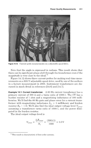
Figure 14.12 Current probe measurements on a adjustable-speed drive.
Note that the angle is expressed in radians. This result shows that
there can be significant phase shift through the transformer even if the
10
magnitude is very close to the ideal.
Figure 14.12 shows three current probes for making real-time meas-
urements on a 600-V adjustable speed drive, used by one of the authors
in a factory measurement in 2005. Instrument transformers are dis-
cussed in much detail in references [14.6] and [14.7].
Example 14.1: Current transformer. A 60 Hz current transformer has a
primary current of 500 A and a turns ratio of 1000:1. The CT has a
burden resistor of 1 ohm and a magnetizing inductance of 100 milli-
henries. We’ll find the 60 Hz gain and phase error for a current trans-
former with magnetizing inductance L 1 millihenry and burden
m
resistor R 1 . We’ll also find the ideal output voltage level V sense ,
B
assuming a transformer turns ratio of 1000:1, and the power dissi-
pated in the burden resistor.
The ideal output voltage level is
I R sense s500ds1d
p
V sense 5 5 5 0.5 V
N s 1000
10
This result is characteristic of first-order systems.