Page 227 - Power Quality in Electrical Systems
P. 227

Power Quality Measurements  209


           I s

                                      +

                                 R  V
                     L m           B  sense
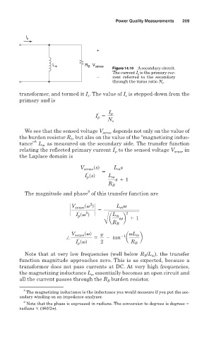
                                            Figure 14.10 A secondary circuit.
                                            The current I s is the primary cur-
                                      –     rent referred to the secondary
                                            through the turns ratio N s .
        transformer, and termed it I . The value of I is stepped-down from the
                                  s
                                                 s
        primary and is
                                          I p
                                       r
                                     I p 5
                                          N s
          We see that the sensed voltage V sense  depends not only on the value of
        the burden resistor R , but also on the value of the “magnetizing induc-
                            b
              8
        tance” L as measured on the secondary side. The transfer function
                 m

        relating the reflected primary current I to the sensed voltage V sense  in
                                             p
        the Laplace domain is
                                V sense ssd  5  L s
                                              m
                                  r
                                 I p ssd  L m
                                             s 1 1
                                          R B
                                  9
          The magnitude and phase of this transfer function are
                                   2
                            V sense sv d     L v
                                               m
                            `  r  2  ` 5
                              I p sv d      L m  2
                                           a   vb 1 1
                                         Ä R
                                             B
                            V sense svd  p     21  vL m
                          /          5   2  tan  a    b
                               r
                              I p svd  2           R B
          Note that at very low frequencies (well below R B /L m ), the transfer
        function magnitude approaches zero. This is as expected, because a
        transformer does not pass currents at DC. At very high frequencies,
        the magnetizing inductance L m essentially becomes an open circuit and
        all the current passes through the R B burden resistor.

          8
           The magnetizing inductance is the inductance you would measure if you put the sec-
        ondary winding on an impedance analyzer.
          9
           Note that the phase is expressed in radians. The conversion to degrees is degrees
        radians   (360/2 ).
   222   223   224   225   226   227   228   229   230   231   232