
Page 226 - Power Quality in Electrical Systems
P. 226
208 Chapter Fourteen
I : N s R w
R c L m
(a)
I : N s
I s
I P
L m
(b)
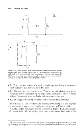
Figure 14.9 Models of a current transformer. (a) Includes parasitic ele-
ments such as core loss resistance R c , magnetizing inductance L m
(referred to the secondary), and secondary winding resistance R w .
(b) Model resulting from the assumption that the core loss and sec-
ondary winding resistance have negligible effects.
■ R : The core loss resistance, which models power dissipation due to
c
eddy currents and hysteresis in the core
■ L : The magnetizing inductance. This is the inductance you would
m
measure if you connected up an impedance analyzer to the secondary
side of the transformer, with the primary open-circuited.
■ R : The copper winding resistance of the secondary winding.
w
In some cases, the core loss and secondary winding loss are negligi-
ble, and we can model the transformer as shown in Figure 14.9b.
7
A model of the secondary circuit is shown in Figure 14.10. In this cir-
cuit, we’ve referred the primary current to the secondary side of the
7
Of course, this more realistic view still ignores many important parasitic effects, includ-
ing secondary winding resistance, core loss, and primary to secondary leakage inductance.