
Page 228 - Power Quality in Electrical Systems
P. 228
210 Chapter Fourteen
V sense
I P
Ideal curve
R B
N S
Actual
curve ω
R B
L m
(a)
V sense
I P
+90°
0°
ω
R B
L m
(b)
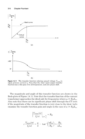
Figure 14.11 The transfer function relating sensed voltage V sense to
input primary current I p . Note that the ideal input-output transfer
function has a flat gain over all frequencies, and zero phase shift.
The magnitude and angle of this transfer function are shown in the
Bode plots of Figure 14.11. Note that the transfer function of the current
transformer approaches the ideal only for frequencies where W R /L .
m
B
Also note that there can be significant phase shift through the CT even
if the magnitude of the transfer function is very close to the ideal. Let’s
examine the transfer function gain and angle in the case of W R /L .
m
B
V sense svd
` ` < R B
r
I p ssd vW R B
L m
svd vL R
V sense p 21 m B
/ 5 2 tan a b <
r
I p svd 2 R B vL m