
Page 76 - Power Quality in Electrical Systems
P. 76
Harmonics and Interharmonics 59
R sys L sys R tr L tr . V LOAD
0.000443 2.81 µH 0.0023 36.6 µH Cbank 6900 µF
V s
0.443 mΩ j(1.06 mΩ) 2.3 mΩ j(13.8 mΩ) −j(384 mΩ)
(a)
600 V
400 V
200 V
0 V
−200 V
−400 V
−600 V
100 ms 110 ms 120 ms 130 ms 140 ms 150 ms 160 ms 170 ms 180 ms 190 ms 200 ms
V(Vline) Time
(b)
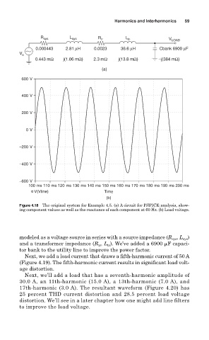
Figure 4.18 The original system for Example 4.5. (a) A circuit for PSPICE analysis, show-
ing component values as well as the reactance of each component at 60 Hz. (b) Load voltage.
modeled as a voltage source in series with a source impedance (R , L )
sys
sys
and a transformer impedance (R , L ). We’ve added a 6900
F capaci-
tr
tr
tor bank to the utility line to improve the power factor.
Next, we add a load current that draws a fifth-harmonic current of 50 A
(Figure 4.19). The fifth-harmonic current results in significant load volt-
age distortion.
Next, we’ll add a load that has a seventh-harmonic amplitude of
30.0 A, an 11th-harmonic (15.0 A), a 13th-harmonic (7.0 A), and
17th-harmonic (3.0 A). The resultant waveform (Figure 4.20) has
25 percent THD current distortion and 28.5 percent load voltage
distortion. We’ll see in a later chapter how one might add line filters
to improve the load voltage.