
Page 149 - Practical Control Engineering a Guide for Engineers, Managers, and Practitioners
P. 149
124 Chapter Five
The last line shows that the denominator of G is a third-order
polynomial in s results, so the system is indeed a third-order sys-
tem. Equation (5-4) also shows that the transfer function G has three
poles at
1
1
1
s=--:z:-, --:r-, t:3
1 2
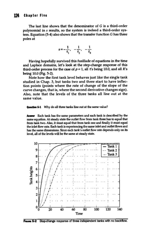
Having hopefully survived this fusillade of equations in the time
and Laplace domains, let's look at the step-change response of this
third-order process for the case of p = 1, all ts being 10.0, and all R's
being 10.0 (Fig. 5-2).
Note how the first tank level behaves just like the single tank
studied in Chap. 3, but tanks two and three start to have inflec-
tion points (points where the rate of change of the slope of the
curve changes, that is, where the second derivative changes sign).
Also, note that the levels of the three tanks all line out at the
same value.
Question S-1 Why do all three tanks line out at the same value?
Anawer Each tank has the same parameters and each tank is described by the
same equation. At steady state the outlet flow from tank three has to equal that
from tank two. Also, it must equal that from tank one and finally it must equal
the inlet flow rate. Each tank is experiencing the same inlet and outlet flows and
has the same dimensions. Since each tank's outlet flow rate depends only on its
level, all of the levels will be the same at steady state.
lOr----.----~~~~~~~~-.======~
··· ·;::..-· -Tank 1
9 .~:···0 0 ,,<. 0 0 0 0 0 0. 0 ... Tank 2
oo'o 0 ,.,
8 _:0 ·o,; 0 0 0 0 0 0 0 0 0 0 0 °- Tank 3
0
"
7 o, 0 0) 0 /: 0 0 0 0 0 0 0 0 0 0 0 0 0 0
00 ; 0
~ 6 :0 / .... · ...... · .
0
0
.!l!P ,'o 01
0
.! 5 0 : 0 0 .' ..
~ ,' I
/ ~/
~ 4
3 .. : 0 ,: ..
0: i 0
2 : 0 j ... ·.· ... ·.
:' i
1 0..:' /
o I
... ;
0 0.
0 20 40 60 80 100 120 140
Tune
FIGURE 5-2 Step-change response of three independent tanks with no backflow.