
Page 147 - Practical Control Engineering a Guide for Engineers, Managers, and Practitioners
P. 147
122 Chapter Five
U = F 0
~
+
Jx,
I
y = x,
f..,
~-
1
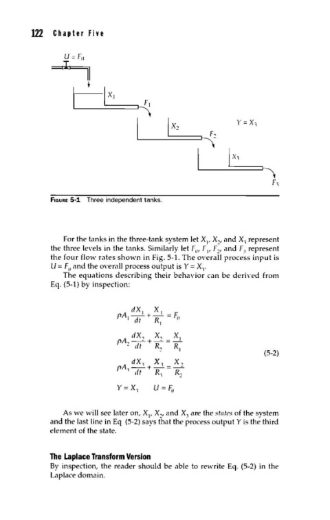
fiGURE 5-1 Three independent tanks.
For the tanks in the three-tank system let XI, x2, and x, represent
the three levels in the tanks. Similarly let Fw F , F , and FJ represent
1 2
the four flow rates shown in Fig. 5-1. The overall process input is
U = F and the overall process output is Y = Xr
0
The equations describing their behavior can be deri\·ed from
Eq. (5-l) by inspection:
dXI XI
f'A~--~-+-R =F;~
ttf I
dX, X.., XI
f'A,-- +-- =-
- dt R R
2 1
(5-2)
dX, X, X,
rA -+-=--
.... dt R, R
2
Y= X u = F;,
1
As we will see later on, X , X , and XJ are the states of the system
1 2
and the last line in Eq (5-2) says that the process output Y is the third
element of the state.
The Laplace Transform Version
By inspection, the reader should be able to rewrite Eq. (5-2) in the
Laplace domain.