
Page 27 - Practical Control Engineering a Guide for Engineers, Managers, and Practitioners
P. 27
2 Chapter One
Llr- Vain?
=L II ~Tank lml
I I IL.....---y -----.
\
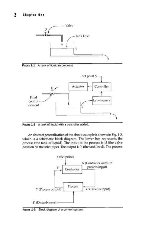
fiGURE 1-1 A tank of liquid (a process).
Set point Sl
U ,..----~lr-A-ct-u-,1-tl-)r----,H Controller
Final f II
control~ 1
element ' y
fiGURE 1-2 A tank of liquid with a controller added.
An abstract generalization of the above example is shown in Fig. 1-3,
·which is a schematic block diagram. The lo·wer box represents the
process (the tank of liquid) The input to the process is ll (the vah·e
position on the inlet pipe). The output is Y (the tank level). The process
S (Sd point)
Process
U (Process input)
0 (Disturbances)-----'
fiGURE 1-3 Block diagram of a control system.