
Page 211 - Practical Machinery Management for Process Plants Major Process Equipment Maintenance and Repair
P. 211
Reciprocating Gas Engines and Compressors 193
This small number of checks does not appear to be much of a preven-
tive maintenance program for reciprocating compressor cylinders but if it
is followed, every critical and moving part can be scrutinized and pro-
tected without shutting the unit down (except for cylinder inspection
through the valve port). Furthermore, no instruments are required other
than the standard gauges and thermometers on every unit.
The program just described is the bare minimum that will fit the small-
est pocketbook. We would not argue with anyone who would want to
spend more, but it is interesting that some would consider it too exten-
sive. However, for this or any program to be successful, a well-trained,
conscientious and cost-minded person must conduct the tests and evaluate.
the operational warning signs and indications, and he must be given the
authority to shut the unit down when the warning signs indicate it should
be done.
Procedures
Although the expendable parts of engines, such as pistons, rings and
valves, have been the subject of many maintenance writeups and proba-
bly are understood by almost everyone, the lower part of the engine,
such as foundation, grout, frame and crankshaft, has not received enough
coverage in the past. Perhaps it is because this area has been relatively
trouble free; however, in the last decade, troubles there have increased.
For this reason, let us look closely at the lower portion of the engine in-
stallation.
Crankshaft deflection, determined by web gauge or inside micrometer,
is the most important indication or test of the condition of the foundation,
grout, frame, crankshaft and main bearings. But in order to be used to
full advantage, the method of conducting this test has to be understood.
Tgking Crankshaft Deflections
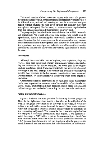
Figure 5-9 shows the exact position for locating the web gauge (A).
Note, in the right-hand view, that it is installed at the midpoint of the
web. If the gauge were installed at the edge of the webs, it would not
follow true web deflection as the crank is rotated. Note in the left-hand
view that the gauge is located a definite distance from the centerline of
the connecting rod journal. The reason for this is that the engine builder
has assigned a maximum deflection to each engine. If the operator lo-
cated the gauge at “B,” which is out on the counterweights, the deflec-
tion recorded there would be twice the actual deflection measured at
“A.” In some installations the rod cap interferes with the gauge as the
crank is rotated, and the instrument has to be located out on the counter-