
Page 212 - Practical Machinery Management for Process Plants Major Process Equipment Maintenance and Repair
P. 212
194 Major Process Equipment Maintenance and Repair
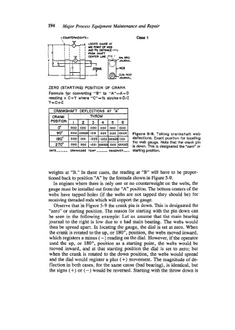
ZERO (STARTING) POSITION OF CRANK
Formula far converting “8” to “A”-A= E
reading x C+Y where %“=H strake+O/t
Y=C+E
Figure 5-9. Taking crankshaft web
deflections. Exact position for locating
the web gauge. Note that the crank pin
is down. This is designated the 2ero” or
starting position.
weights at “B.” In these cases, the reading at “B” will have to be propor-
tioned back to position “A” by the formula shown in Figure 5-9.
In engines where there is only one or no counterweight on the webs, the
gauge must be installed out from the “A” position. The bottom centers of the
webs have tapped holes (if the webs are not tapped they should be) for
receiving threaded rods which will support the gauge.
Observe that in Figure 5-9 the crank pin is down. This is designated the
“zero” or starting position. The reason for starting with the pin down can
be seen in the following example: Let us assume that the main bearing
journal to the right is low due to a bad main bearing. The webs would
then be spread apart. In locating the gauge, the dial is set at zero. When
the crank is rotated to the up, or 180°, position, the webs moved inward,
which registers a minus (-) reading on the dial. However, if the operator
used the up, or 180°, position as a starting point, the webs would be
moved inward, and at that starting position the dial is set to zero; but
when the crank is rotated to the down position, the webs would spread
and the dial would register a plus (+) movement. The magnitude of de-
flection in both cases, for the same cause (bad bearing), is identical, but
the signs (+) or (-) would be reversed. Starting with the throw down is