
Page 214 - Practical Machinery Management for Process Plants Major Process Equipment Maintenance and Repair
P. 214
1% Major Process Equipment Maintenance and Repair
CRANK THROW
-POSITION 1 2 1 3 4 5 6
0' 000 000 ' 000 000 ' 000 000
- . -.0005 -.0015 -.001 - .0005 000
90"
--.00025
-
180" -.001 -.003 -.006 1 -.004 --.C015 000
270' 000 -.@I025 -.0015 i -A01 -. 0 0025 000
CASE NO. 3-SAME AS ABOVE EXCEPT ALL SIGNS (+)
CASE NO. 4
CRANK THROW
POSITION 1 2 3 4 5 6
0" 000 000 000 I 000 000 000
90" --.00025 -A015 000 I +.Oil025 +.0015 +.0002!
180' -.001 -.004 --.OOOS I +.001 I f.005 f.001
270" -.00025 --.(IO1 000 ! 000 I , +.001 000
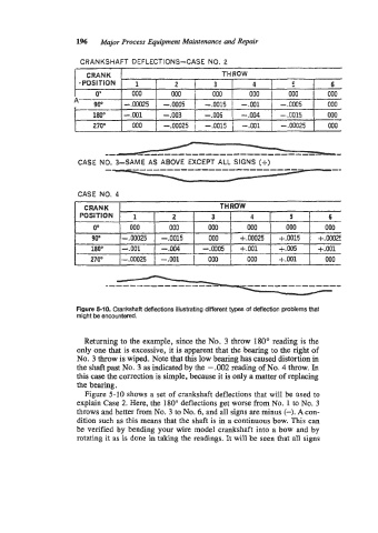
Flgure 5-10. Crankshaft deflections illustratlng different types of deflection problems that
might be encountered.
Returning to the example, since the No. 3 throw 180" reading is the
only one that is excessive, it is apparent that the bearing to the right of
No. 3 throw is wiped. Note that this low bearing has caused distortion in
the shaft past No. 3 as indicated by the - .002 reading of No. 4 throw. In
this case the correction is simple, because it is only a matter of replacing
the bearing.
Figure 5-10 shows a set of crankshaft deflections that will be ased to
explain Case 2. Here, the 180" deflections get worse from No. 1 to No. 3
throws and better from No. 3 to No. 6, and a11 signs are minus (-). A con-
dition such as this means that the shaft is in a continuous bow. This can
be verified by bending your wire model crankshaft into a bow and by
rotating it as is done in taking the readings. It will be seen that all signs