
Page 229 - Practical Machinery Management for Process Plants Major Process Equipment Maintenance and Repair
P. 229
Reciprocating Gas Engines and Compressors 211
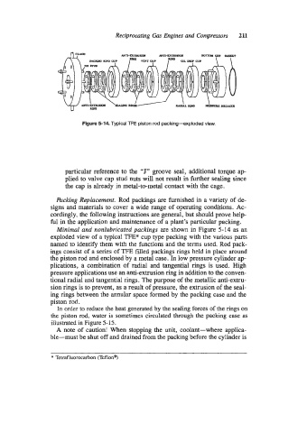
Figure 5-14 Typical TFE piston rod packing--exploded view,
particular reference to the “J” groove seal, additional torque ap-
plied to valve cap stud nuts will not result in further sealing since
the cap is already in metal-to-metal contact with the cage.
Packing Replacement. Rod packings are furnished in a variety of de-
signs and materials to cover a wide range of operating conditions. Ac-
cordingly, the following instructions are general, but should prove help-
ful in the application and maintenance of a plant’s particular packing.
Minimal and nonlubricated packings are shown in Figure 5-14 as an
exploded view of a typical TFE* cup type packing with the various parts
named to identify them with the functions and the terms used. Rod pack-
ings consist of a series of TFE filled packings rings held in place around
the piston rod and enclosed by a metal case. In low pressure cylinder ap-
plications, a combination of radial and tangential rings is used. High
pressure applications use an anti-extrusion ring in addition to the conven-
tional radial and tangential rings. The purpose of the metallic anti-extru-
sion rings is to prevent, as a result of pressure, the extrusion of the seal-
ing rings between the annular space formed by the packing case and the
piston rod.
In order to reduce the heat generated by the sealing forces of the rings on
the piston rod, water is sometimes circulated through the packing case as
illustrated in Figure 5-15.
A note of caution! When stopping the unit, coolant-where applica-
ble-must be shut off and drained from the packing before the cylinder is
* Tetraf luorocarbon (Tef lona)