
Page 266 - Practical Machinery Management for Process Plants Major Process Equipment Maintenance and Repair
P. 266
248 Major Process Equipment Maintenance and Repair
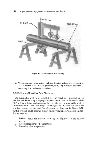
Figure 6-23. Checking indicator arm sag.
2. When changes in indicator readings dictate, reduce sag by keeping
“G” dimension as short as possible, using light-weight indicators,
and using one indicator at a time.
Establishing and Checking Final Alignment
An acceptable method of establishing and checking alignment in the
ambient condition is by clamping a spanner arm to one of the shafts (shaft
“B” in Figure 6-24) and spanning the indicator arm across to the mating
shaft or coupling hub. For flanged couplings, use two dial indicators for
reading outside diameter and face alignment as illustrated in Figure 6-24.
(Other types of coupiings may require set-up variations.) Proceed in the fol-
lowing manner:
1. Perform check for indicator arm sag (see Figure 6-23 and related
section).
2. Record approximate “R’ dimension.
3. Record ambient temperature.