
Page 343 - Practical Machinery Management for Process Plants Major Process Equipment Maintenance and Repair
P. 343
Installation and Maintenance of VBelt Drives 323
$1
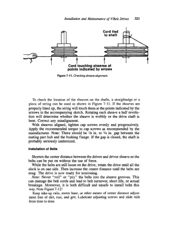
I Cord touching sheaves at
points indicated by amws
Figure 7-11. Checking sheave alignment.
To check the location of the sheaves on the shafts, a straightedge or a
piece of string can be used as shown in Figure 7-1 1. If the sheaves are
properly lined up, the string will touch them at the points indicated by the
arrows in the accompanying sketch. Rotating each sheave a half revolu-
tion will determine whether the sheave is wobbly or the drive shaft is
bent. Correct any misalignment.
With sheaves aligned, tighten cap screws evenly and progressively.
Apply the recommended torque to cap screws as recommended by the
manufacturer. Note: There should be 118 in. to 1/4 in. gap between the
mating part hub and the bushing flange. If the gap is closed, the shaft is
probably seriously undersized.
Installation of Belts
Shorten the center distance between the driven and driver sheave so the
belts can be put on without the use of force.
While the belts are still loose on the drive, rotate the drive until all the
slack is on one side. Then increase the center distance until the belts are
snug. The drive is now ready for tensioning.
Note: Never “roll” or “pry” the belts into the sheave grooves. This
can damage the belt cords and lead to belt turnover, short life, or actual
breakage. Moreover, it is both difficult and unsafe to install belts this
way. Note Figure 7-12!
Keep take-up rails, motor base, or other means of center distance adjust-
ment free of dirt, rust, and grit. Lubricate adjusting screws and slide rails
from time to time.